Blog - 13: Solar Panel Connectors – 25‑Year Uninterrupted Connection: From Metal Selection to Extreme Validation, Every Step Is Quantified
Solar Panel Connectors MC4 – 25‑Year Uninterrupted Connection: From Metal Selection to Extreme Validation, Every Step Is Quantified
In photovoltaic power plants, PV module connectors MC4 are numerous yet easily overlooked. A 100 kWp plant typically requires 600 to 1,000 such solar connectors. Their contact resistance, tensile strength, and environmental durability directly determine DC side losses and system safety. A 25‑year service life is not just a slogan—it is a strict commitment that must be fulfilled through material selection, micro‑scale structural design, and rigorous testing. This article breaks down the quality core of high‑performance MC4 connectors from three perspectives: base material and plating, terminal geometry, and third‑party test data.
1. Scientific Material Selection – The “Golden Combination” of Copper Substrate and Coating
1.1 Base Material: High‑Performance Brass T3
T3 brass is chosen for its excellent electrical conductivity, work‑hardening capability, and resistance to stress relaxation. Under long‑term thermal cycling, it maintains stable elastic contact pressure, preventing resistance rise due to creep.
1.2 Coating: Bright Tin, Precisely Controlled at 3–8 μm
-
Oxidation protection: The dense tin layer isolates the copper from air, achieving ≥48 hours of salt‑spray resistance without corrosion—easily coping with coastal and industrial polluted environments.
-
Resistance reduction: Low contact resistance minimises heating and improves transmission efficiency.
-
Solderability: The bright tin surface offers good wettability, making it compatible with both crimping and soldering processes in the field.
2. Structural Design – Micron‑Level Precision for 25‑Year Stable Contact
2.1 Multi‑Point Elastic Contact – Redundant Channels, No Interruption on Failure
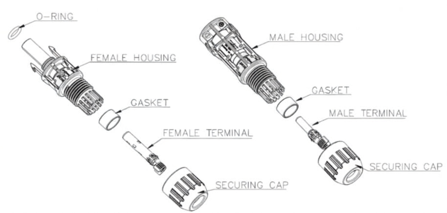
The PV connector employs a stamped elastic cage or torsion‑spring structure (similar to STAUBLI’s MULTILAM technology) with four independent elastic arms that create multiple parallel contact points. Even if a single contact point temporarily fails due to vibration or thermal cycling, the remaining contacts still maintain continuity—achieving true redundant contact.
2.2 Quantified Parameters – Balancing Performance and Handling
-
Contact normal force ≥20 N: Too low a force causes contact‑resistance fluctuation; too high a force impairs field plug‑in/out experience.
-
Insertion force ≤80 N, withdrawal force ≥40 N (set to high‑industry standards): ensures smooth installation while maintaining sufficient clamping force to prevent fretting wear.
2.3 Anti‑Slip and Anti‑Backout Structure – Tensile Strength ≥300 N
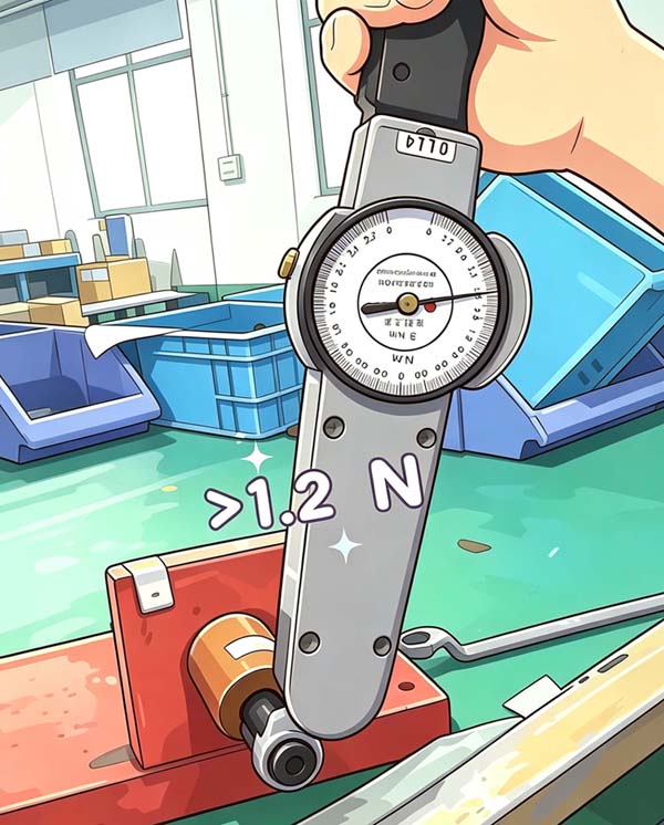
The terminal tail crimping zone features barbs and grooves. With proper crimping tools, the tensile strength after crimping for a 4 mm² solar cable reaches ≥300 N. This structure effectively resists vibration‑induced loosening and cable pulling forces, eliminating the risk of poor contact.
3. Reliability Verification – Proving “25‑Year Uninterrupted” with Data
Material and design are the foundation, but only through stringent testing can the “25‑year” promise be transformed from theory into a verified guarantee.
3.1 Contact Resistance Test (IEC 60512)
At rated current 43 A, initial contact resistance ≤0.5 mΩ. After 200 thermal cycles (–40 °C to +85 °C), the change rate is ≤±20 %, demonstrating that the contact interface remains low‑resistance and stable under extreme temperature differentials.
3.2 Dynamic Vibration and Shock Test (IEC 62852)
During the test, the instantaneous contact resistance interruption time is <1 μs, proving that the elastic structure never loses continuity under continuous mechanical stress—especially critical for ground‑mount plants subject to wind, sand, and vehicle‑induced vibrations.
3.3 Salt‑Spray and Ageing Tests
-
Neutral salt‑spray (IEC 60068‑2‑11) for 72 hours: contact resistance remains ≤0.6 mΩ, with no red rust on the appearance—far exceeding basic requirements.
-
Thermal ageing (UL 486E, 120 °C, 300 h): verifies the diffusion‑barrier performance between the tin coating and the copper substrate, ensuring that the plating does not degrade under long‑term high‑temperature operation.
3.4 Third‑Party Authoritative Reports
All tests are accompanied by independent terminal test reports issued by TUV, UL, or SGS, serving as traceable evidence that gives purchasers and EPC contractors full confidence in their selection.
Conclusion
From T3 brass substrate and 3–8 μm bright tin plating, to a ≥20 N contact normal force and 4‑point elastic redundant structure, and through to complete IEC and UL‑compliant verification—every set of data answers the same question: how to keep an MC4 connector performing reliably outdoors for 25 years. When selecting connectors, do not look only at price; always verify the material grade, structural parameters, and third‑party reports. Only quantified quality can underpin the long‑term returns of a PV plant.
Blog - 14 : Say Goodbye to Overheating – TYOU Solar Junction Box with Smarter Cooling
Blog - 12: From the Source – Plastic Raw Materials Determine Service Life: TYOU Solar PV Connector 25-Year Reliability Assurance